Acoustic Model
RoomAcoustiC++ implements a hybrid geometric acoustic and feedback delay network model for simulating sound propagation in rooms.
The Image Edge Model1 is used to simulate early reflections and diffraction. The maximum reflection order and diffraction orders can be configured independently to control the complexity of the model.
Late reverbation is modelled using efficient Feedback Delay Networks5 (FDNs) with two different models included in the library. The first (SingleFDN) is based on the RAZR model proposed by Wendt et al.2 with modifications to support diffraction and non-shoebox rooms. This uses a single FDN to create the late reverbation exponential decay.
The second late reverberation model (RAVES) is based on the MoD-ART model proposed by Scerbo et al.3. This renders late reverbation using multiple FDNs and therefore is suitable for more complex environments with directional and position dependent reverbation, double slope effects and multiple sources in uniquely reverberant rooms.
The following section provides an overview of the key components of the acoustic model.
Image Edge Model
The Image Edge Model1 is a geometric acoustic approach for simulating early reflections and diffraction in room acoustics.
It extends the classic Image Source Model4 by incorporating edge diffraction, enabling more realistic spatial audio rendering in complex environments.
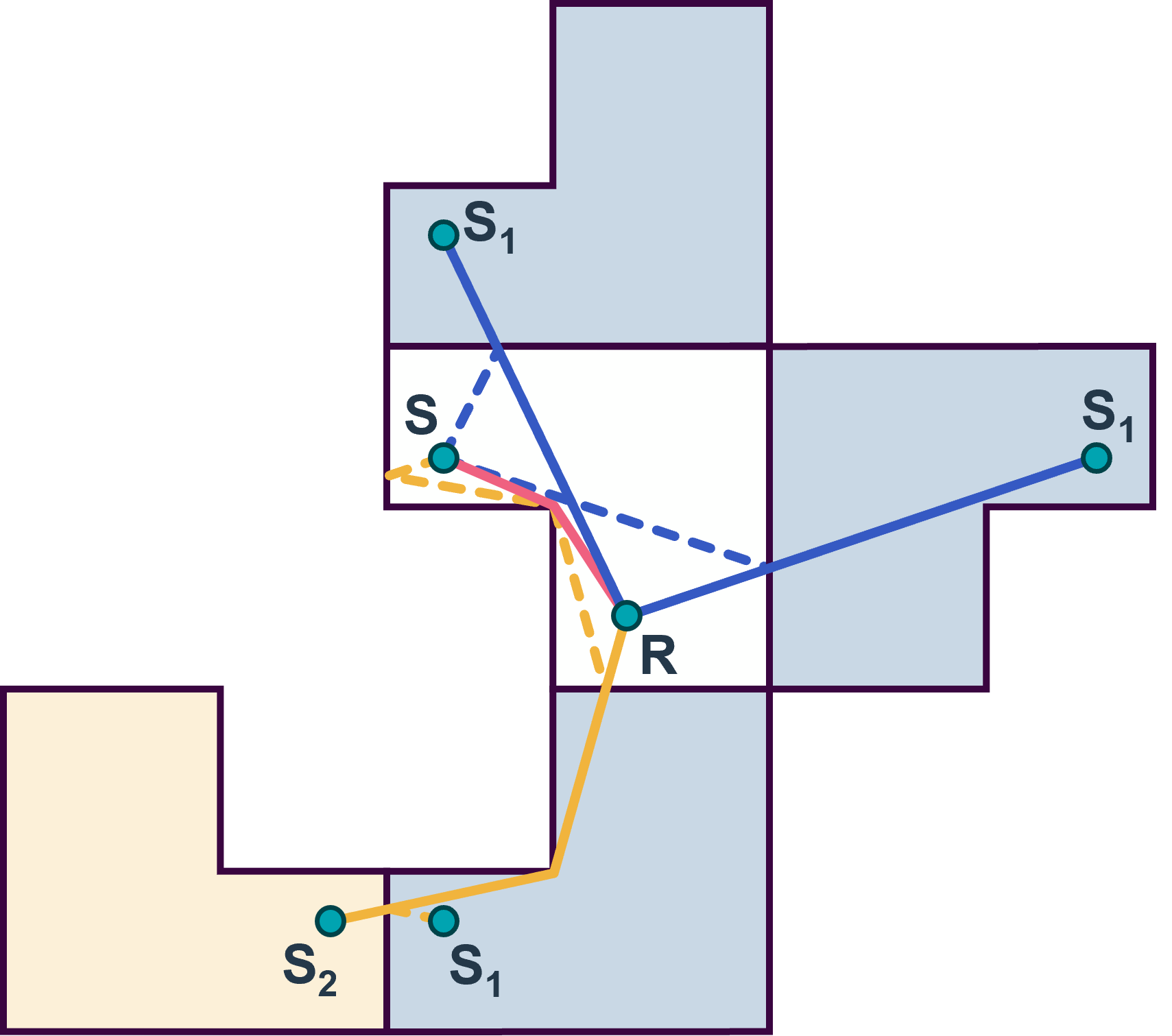
Figure 1: Image Edge Model diagram showing source, listener, and image sources.
Early reflections are modeled by treating each wall as a mirror that creates virtual image sources. For each reflection order, the position of the image source is calculated by mirroring the real source across the room's surfaces. The listener receives sound from both the direct source and its images, with each path having a distinct delay, attenuation, and direction. For each reflection path, the received signal at time (\(t\)) is given by: $$ y(t) = \frac{(h * x)\left[t - \frac{r}{c}\right]}{r}, $$ where
- \(h[\cdot]\) is a frequency-dependent filter,
- \(x[\cdot]\) is the anechoic input signal,
- \(r\) is the distance from the receiver,
- \(c\) is the speed of sound,
- \(*\) denotes convolution.
In arbitrary polyhedral rooms, each image source must be checked for valid intersections and then visibility to the listener. Each image source can be spatialised by applying a HRTF, or other panning technique based on the direction of arrival.
Real rooms contain obstacles and edges that bend sound waves, producing diffraction. The Image Edge Model augments the image source approach by creating virtual image edges. These are reflected in the same way as image sources and can be used to create diffraction paths from image sources. This allows the model to locate sound paths that include both diffraction and reflections. RAC currently only supports 1st-order diffraction but an extension to higher orders is planned.
The Image Edge Model can be configured with the following parameters:
- Direct sound: None, Check for obstructions, Always visible (i.e do not check for obstructions).
- Reflection Order: The maximum order paths including only reflections.
- Shadow Diffraction Order: The maximum order of paths including shadowed diffraction.
- Specular Diffraction Order: The maximum order of paths including non-shadowed edge diffraction.
- Minimum Edge Length: The minimum length of edges to consider for diffraction.
Feedback Delay Network
Feedback Delay Networks5 (FDNs) are used to mimic the natural decay of sound for late reverberation by controlling the decay time and frequency response of late reverberation. They use a recursive structure with multiple delay lines allowing for efficient processing independent of the reverberation time.

Figure 1: SingleFDN Feedback Delay Network diagram. Each path represents multiple delay lines and A is a mixing matrix that controls the feedback between delay lines.
In SingleFDN implementation the highest order image sources are used as inputs to an FDN to simulate late reverberation. The FDN is configured using the room dimensions and either Sabine or Eyring formulas to predict the frequency-dependent reverberation time. Alternatively, the reverberation time can be set manually.
The absorption filters are used to control the frequency dependent decay time based on the decay of each delay line. The output of the FDN is spatialised by placing reverb sources around the the listener and applying a HRTF (or other panning technique) based on the direction relative to the listener. The reflection filters are set to the absorption of the nearest wall in the direction of the reverb source linked to each respective FDN channel. This simulates directional late reverberation, for example, if the listener is beside an absorbative wall, less reverberation will be heard from that direction.
The FDN can be configured with the following parameters:
- Matrix: Householder, RandomOrthogonal
- Room dimensions: The dimensions of the room in meters (for a shoebox room this would be the width, height, depth). These determine the delay line lengths.
- Number of delay lines/reverb sources: Determined the number of delay lines in the FDN and the number of reverb sources. A larger number increases the computational cost of the FDN but can improve the quality of the reverberation.
MoD-ART (RAVES)
MoD-ART (Modal Decomposition of Acoustic Radiance Transfer) is an alternative late reverberation model that can be used instead of the single FDN.
It is based on precomputed data generated by analyzing the acoustic environment.
The offline analysis provides the reverberation times of different parts of the environment, while runtime ray-tracing informs the effect of each sound source and listener on each reverberation component.
Different components are modeled by separate FDNs and can also be frequency dependent.
In the public API it is initialised using InitMoDART(const MoDARTData& data), where MoDARTData contains the precomputed data required by the model.
More information about the workings of MoD-ART can be found here.
-
Erraji A, et al. "The image edge model." Acta Acust., 2021, 5:1-15, 2021. ↩↩
-
Wendt T, et al. "A computationally-efficient and perceptually-plausible algorithm for binaural room impulse response simulation." J. Audio. Eng. Soc., 62:748-766, 2014. ↩
-
Scerbo M, et al. "Efficient multichannel auralization based on the modal decomposition of acoustic radiance transfer." IEEE Trans. on Audio, Speech and Lang. Proc., 33:4748-4759, 2025 ↩
-
Borish J. "Extension of the image model to arbitrary polyhedra." J. Acoust. Soc. Am., 75:1827–1836, 1984. ↩
-
Jot J, and Chaigne A. "Digital delay networks for designing artificial reverberators." Proc. Audio Eng. Soc. Conv., Paris, France. 1-12, 1991. ↩↩